Abstract
The centralized control architecture for railway signal drivers often experiences unstable supply voltage and insufficient drive current due to the extended length of signal cables. Furthermore, the high inrush currents during the operation of conventional electromechanical relays can damage signal machines and reduce their service life. To address these issues, this paper presents a relay-free drive module for DC signal machines based on a distributed system. The module integrates remote communication and safety control technologies, enabling the deployment of safety execution units trackside. It utilizes power-driven DC-DC conversion technology, replacing relay-based control circuits to ensure safe driving of DC signals. Based on the "fail-safe"principle, the module incorporates circuit self-testing and closed-loop drive control to guarantee secure and reliable operation. The intelligent control core employs a heterogeneous dual-channel (2oo2) architecture using System-on-Chip (SoC) technology to enhance security and mitigate common-cause failures. Experimental verification confirms that the proposed module delivers highly stable and programmable DC output voltage across a wide input range, demonstrating excellent voltage regulation and controllability via Pulse Width Modulation (PWM). The all-electronic design eliminates contact arcing and inrush current, while integrated real-time monitoring and self-diagnostic capabilities ensure operational safety and reliability. These results underscore the module's strong potential for practical application in modern distributed trackside control systems, offering advantages in system simplification, maintenance reduction, and enhanced equipment longevity.
Keywords
DC Signal Machine, Distributed Railway System, Relay-free Drive Module, DC-DC Conversion, Closed-loop Drive Control
1. Introduction
As the command center of rail transit control systems, signaling lights are essential equipment for ensuring train safety and modernizing operations. With the increase in train speeds, the safety and reliability requirements for rail transit signals have become increasingly stringent
| [1] | Pan M, Zhao M Y, Wang L S. Research on Intelligent Switch Machine for Distributed Electronic Computer Interlocking System. Railway Standard Design. 2018, 62(11): 134-138.
https://doi.org/10.13238/j.issn.1004-2954.201710270001 |
| [2] | Zhao Z J. Exploration of Centralized Control Scheme for Computer Interlocking Equipment. Railway Communication Signal. 2014, 50 (4): 12-13, 18. |
| [3] | Xue Z H. Application of Intelligent Analysis System for Indoor and Outdoor Operation Status of Railway Signal Machine. Transportation World. 2025 (9): 18-20.
https://doi.org/10.3969/j.issn.1006-8872(s).2025.09.006 |
[1-3]
. Current signal control systems predominantly use centralized configurations, placing signal lights and control units in outdoor fields and indoor control centers respectively
. However, variations in signal cable lengths and unstable power supply often lead to voltage fluctuations and insufficient drive currents, which shorten signal machine lifespan. The extensive use of cables also increases risks of cable entanglement and complicates maintenance
. Additionally, most existing signal drivers contain relays, whose instantaneous high currents during switching can damage signals
, reduce service life, and increase maintenance complexity and costs
. Future railway signaling systems will integrate advanced communication technologies like wireless and fiber-optic networks
, deploying safety execution units at trackside locations. By establishing interconnections between independent devices, these systems will achieve integrated communication
| [12] | Li S. Analysis and Optimized Design of Approach Signal Lighting Circuit of a Station. Railway Signalling & Communication Engineering. 2023, 20(8), 90-94.
https://doi.org/10.3969/j.issn.1673-4440.2023.08.017 |
| [13] | Zhang Y X. Research on the Control Module of Train Signal of Distributed Computer Interlocking System of Railway Station. Master's thesis, Lanzhou Jiaotong University, 2014.
https://doi.org/10.7666/d.D539288 |
| [14] | Cheng R, Ren X G, Xing M L, Liu H Y. Design of Distributed Switch Controller System. Railway Signalling & Communication Engineering. 2024, 21(8), 86-91.
https://doi.org/10.3969/j.issn.1673-4440.2024.08.014 |
| [15] | Wu F, Wang G. Analysis and Solution of Communication Faults between Computer Interlocking and Fully Electronic Execution Unit. Railway Communication Signal. 2016, 52 (2): 84-86. https://doi.org/10.13879/j.issn1000-7458.2016-02.15546 |
[12-15]
.
2. Module Architecture and Overview
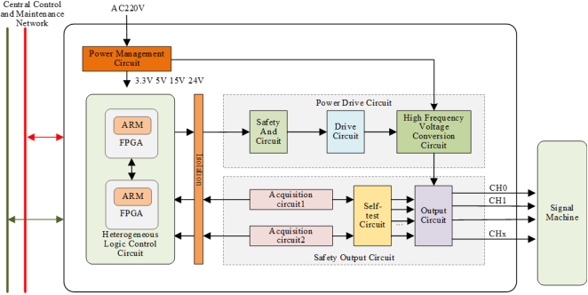
Figure 1. Structure diagram of relay-free DC signal machine drive module.
The drive module for DC signal machine without relay (hereinafter referred to as the drive module), serving as the core component of the distributed signal control system, is installed at outdoor sites. It generates power on-site and connects to a remote control center via network to receive command signals, control the signal machine, and upload monitoring data. The drive module primarily performs the following functions:
1. Receive the remote control command and execute the command after "fail-safe" comparison.
2. Control voltage conversion according to the control command to realize the driving voltage output.
3. Real-time acquisition of current and voltage to achieve output monitoring and stable voltage output.
4. Carry out self-test of periodic drive circuit, and cut off output when abnormal.
5. Periodically report module working status and monitoring information such as driver output.
The structure of the driver module is shown in
Figure 1. The intelligent control part of the drive module is a heterogeneous logic control circuit, which receives remote control commands and completes closed-loop control and self-test of the drive circuit according to the acquisition of junctions. The driving part of the drive module is the power driving circuit, which replaces the conventional relay with an all-electronic design and converts the rail-side AC220V input into the DC driving voltage of the DC Signal Machine; the output and acquisition part of the drive module is the safety output circuit, which can satisfy the safety driving control of the Signal Machine with multiple light positions, and the real-time acquisition of the output result can realize the voltage stabilization output and the self-checking of the circuit.
3. Hardware Design
3.1. Power Management Circuit
The power management circuit takes power from the AC220V voltage beside the rail. One channel converts the input voltage through the power conversion module to provide weak power supply for other circuits; the other channel serves as the input of the high-frequency voltage conversion circuit to complete the drive voltage conversion.
3.2. Heterogeneous Logic Control Circuit
The heterogeneous logic control circuit employs a fully independent two-out-of-two ("2oo2") architecture to ensure system safety. By comparing remote communication data and input/output data such as drive output voltage/current feedback, it detects anomalies and immediately halts output. The core of this circuit utilizes an System-on-Chip (SOC) chip that integrates both a CPU and FPGA, featuring compact size and low power consumption. The CPU handles logical operations like binary comparisons, while the FPGA leverages its parallel processing capabilities and higher frequency to manage sampling and control switching frequencies with greater precision. The heterogeneous logic control circuit adopts a multi-platform design, where the core SOC modules in dual units utilize different manufacturers' SOC chips, This configuration achieves hardware heterogeneity and compiler diversity, effectively reducing common-mode failure probability and enhancing system security.
3.3. Power Drive Circuit
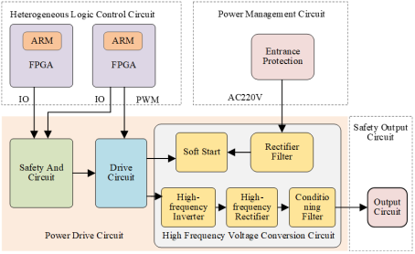
The power drive output circuit is shown in
Figure 2, which includes the safety and circuit, the drive circuit and the high frequency voltage conversion circuit.
Figure 2. Power drive circuit.
In the drive circuit, the drive chip is controlled by dual SOC output PWM wave, so as to realize the control of high-frequency inverter circuit by software and complete voltage conversion. The control mode is flexible and the output voltage can be flexibly configured according to the model of DC signal machine.
The safety and circuitry utilize a two-stage series-connected dynamic design. The dual-stage dynamic circuit employs heterogeneous input architecture, with the CPU in SOC1 and FPGA in SOC2 controlling the electronic switches respectively. Voltage supply to the drive circuit is contingent on simultaneous valid activation from both drivers. In the event of any driver malfunction, subsequent circuits cease output, ensuring operational safety during any SOC failure.
The high-frequency voltage conversion circuit employs power-driven DC-DC conversion technology, controlled by driver chips in the control circuit. It converts 220V AC input into stable DC output through high-frequency voltage conversion. The high-frequency transformer in the circuit not only performs voltage conversion but also provides electrical isolation. When abnormalities occur in either the primary or secondary circuit (such as short circuits or overvoltages), they are not transmitted to the other side, enhancing system safety. The software start-up circuit in the circuit uses an electronic switche to gradually activate through software control, effectively addressing current surge issues during signal equipment power-on. This approach keeps startup current within normal operating ranges, significantly reducing electrical shock effects.
3.4. Safety Output Circuit
The safe output circuit includes the acquisition circuit, the output circuit and the self-test circuit.
The acquisition circuit includes acquisition circuit 1 and acquisition circuit 2, which are respectively connected to SOC1 and SOC2 of heterogeneous logic control circuit. The two SOC complete the acquisition and result judgment respectively.
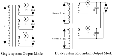
The output circuit employs a multi-winding transformer voltage output configuration, enabling multi-lamp-position operation. Each signal lamp position is powered by its own transformer winding, ensuring isolated operation with no interference between positions. This design eliminates wiring conflicts and reduces mutual effects caused by lamp position failures, achieving independent and secure signal output for each station. The system supports both single-system operation and dual-system redundant configurations, as illustrated in
Figure 3. The dual-system redundancy configuration utilizes parallel output connections, where independent drivers from each system are connected in parallel to form redundant outputs. This design guarantees stable signal illumination even during single-system failures, significantly enhancing system availability.
Figure 3. Output circuit.
As shown in
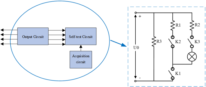
Figure 4, the self-test circuit utilizes electronic switches to enable self-inspection of the drive circuit and fault localization of signal lights through low-voltage and low-current data acquisition. This ensures reliable output accuracy while maintaining proper signal indication. By detecting each lamp position's output, the system identifies faults to prevent signal failures caused by filament breakage or aging.
Figure 4. Self-test circuit.
4. Software Design
Software design includes two parts: CPU and FPGA software. The CPU and FPGA communicate with each other through AHB bus. According to the characteristics of CPU and FPGA, the CPU is mainly responsible for logic operation and control, while FPGA is responsible for drive and execution.
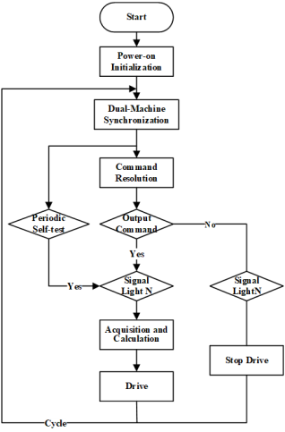
Figure 5. CPU software design flow chart.
As the control "brain", CPU software primarily handles command reception and monitoring reporting. It implements closed-loop control and self-check calculations based on collected voltage data, along with logical design for the "2oo2" safety architecture. The software design flowchart is shown in
Figure 5. Upon system power-up, initialization processes include hardware/software setup, configuration initialization, and power-on self-checks. After initialization, periodic dual-machine synchronization completes all input/output data processing through "2oo2" operations. Following synchronization, it parses approved commands from the remote control center and executes drive outputs based on command content and signal indicator status. During output execution, real-time monitoring of data collection enables closed-loop adjustments to stabilize drive outputs. Closed-loop control employs voltage current detection: voltage deviations are calculated through closed-loop calculations using collected voltage data, while current serves as detection information. This phase-based adjustment method ensures stable and accurate voltage output. Periodic self-checks utilize low current/low voltage configurations, outputting minimal drive voltages for circuit safety verification.
FPGA software primarily functions as the underlying execution software, handling electronic switch control in current/voltage acquisition, power drive circuits, and safety output circuits. When controlling these electronic switches, the software employs slow-on and slow-off mechanisms to prevent voltage spikes during output drive operations. This approach reduces surge currents caused by voltage fluctuations in DC signal machine modules, thereby protecting the circuitry and extending the service life of the signal equipment.
5. Experimental Verification and Results
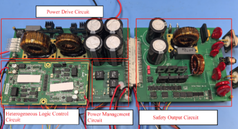
In order to verify the driver module, the output of the driver module is connected to the simulated load, and the function verification and performance evaluation of the driver module are carried out through the simulated load. The experimental environment is shown in
Figure 6.
Figure 6. Experimental environment.
Under the condition of fixed PWM wave duty cycle of 40%, the corresponding output voltage Vout is measured by adjusting the input voltage Vin as shown in
Table 1.
Table 1. Output voltage at 40% duty cycle.
Input voltage | Output voltage | AD input voltage | AD Count | Calib. Factor |
40 | 19.13 | 0.492 | 1608 | 0.01189 |
75 | 35.18 | 0.9 | 2941 | 0.01196 |
102 | 47.69 | 1.215 | 3973 | 0.01200 |
143 | 66.8 | 1.698 | 5553 | 0.01202 |
190 | 88.6 | 2.244 | 7343 | 0.01206 |
212 | 99.1 | 2.51 | 8207 | 0.01207 |
229 | 107.1 | 2.709 | 8863 | 0.01208 |
244 | 113.7 | 2.875 | 9403 | 0.01209 |
When the typical input voltage Vin (AC100V, AC150V, AC220V) is applied, the corresponding output voltage Vout is measured by adjusting the PWM wave duty ratio as shown in
Table 2.
Table 2. Output voltage at different duty cycles of fixed voltage.
Input voltage | Duty cycle | Output voltage | AD input voltage | AD Count | Calib. Factor |
100 | 25 | 22.93 | 0.59 | 1929 | 0.011886 |
40 | 32.47 | 0.83 | 2714 | 0.011963 |
60 | 46.75 | 1.191 | 3895 | 0.012002 |
80 | 62.4 | 1.588 | 5192 | 0.012018 |
150 | 25 | 33.6 | 0.858 | 2804 | 0.011982 |
40 | 48.27 | 1.228 | 4015 | 0.012022 |
60 | 70.46 | 1.792 | 5858 | 0.012027 |
80 | 93.19 | 2.363 | 7725 | 0.012063 |
220 | 25 | 48.79 | 1.241 | 4059 | 0.012020 |
40 | 70.51 | 1.788 | 5847 | 0.012059 |
60 | 102.76 | 2.612 | 8542 | 0.012029 |
80 | 136.1 | 3.445 | 11275 | 0.01207 |
To evaluate the overall performance of the proposed driving module, systematic tests were conducted to assess its output voltage stability and controllability under varying input voltages and PWM duty cycles. The experimental results conclusively validate the key performance characteristics of the module:
1. High Stability: The module demonstrates exceptional output voltage stability against a wide range of input voltages (40V-244V), with minimal variation in calibration factors (<0.2%). This validates the robustness of the closed-loop control system.
2. Programmable Output: A strong linear relationship between the PWM duty cycle and the output voltage is observed. This enables flexible software-configurable output, allowing the module to drive various DC signal machines with different voltage requirements.
3. Reliable Monitoring: The consistency of the sensor coefficients across all test conditions underscores the reliability of the acquisition circuitry, forming a trustworthy foundation for real-time monitoring and fault-safe operation.
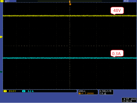
In order to verify the function of the drive signal machine of the drive module, the output of the drive module is connected to the 48V DC traffic signal machine. The voltage and current output by the drive module are observed through the oscilloscope. The experimental results are shown in
Figure 7 (yellow: output voltage is about 48V, green: output current is about 0.3A).
Figure 7. Output voltage and current of the driver module.
In summary, the experimental data consistently demonstrates that the proposed driver module not only meets the core requirements for voltage output stability and flexibility in distributed trackside control but also, through its all-electronic design and integrated monitoring mechanisms, provides strong support for achieving high safety and reliability.
6. Conclusion
This paper has presented the design and implementation of a relay-free drive module for DC signal machines, which serves as a core component for distributed railway control systems. The module offers significant advantages over traditional relay-based solutions:
1. It enables remote distributed control, integrating command reception, fail-safe execution, and circuit self-testing, leading to simplified wiring and reduced installation costs.
2. The relay-free, all-electronic power conversion design eliminates contact arcing and inrush currents, thereby enhancing equipment reliability, reducing maintenance complexity, and extending the service life of signal machines.
3. Real-time closed-loop control of voltage and current ensures stable output and enables continuous monitoring, guaranteeing operational safety.
4. Comprehensive software-driven self-testing and fault localization capabilities enhance system maintainability and ensure fail-safe output.
5. The redundant "2oo2" heterogeneous architecture effectively mitigates single-point failures, significantly improving system availability and operational safety.
Experimental results have confirmed the module's excellent voltage regulation, stability, and programmability. Future work will focus on field trials and long-term reliability testing in operational railway environments.
Abbreviations
PWM | Pulse Width Modulation |
2oo2 | Two-out-of-two |
CPU | Central Processing Unit |
FPGA | Field Programmable Gate Array |
DC | Direct Current |
AC | Alternating Current |
SOC | System on Chip |
Acknowledgments
This section serves to recognize contributions that do not meet authorship criteria, including technical assistance, donations, or organizational aid. Individuals or organizations should be acknowledged with their full names. The acknowledgments should be placed after the conclusion and before the references section in the manuscript.
Author Contributions
Shumin Ge: Data curation, Validation, Software, Writing – original draft, Writing – review & editing
Meili Xing: Data curation, Resources
Yimin Wang: Conceptualization, Methodology
Binbin Huang: Investigation, Methodology
Data Availability Statement
The data is available from the corresponding author upon reasonable request.
The data supporting the outcome of this research work has been reported in this manuscript.
Conflicts of Interest
The authors declare no conflicts of interest.
References
| [1] |
Pan M, Zhao M Y, Wang L S. Research on Intelligent Switch Machine for Distributed Electronic Computer Interlocking System. Railway Standard Design. 2018, 62(11): 134-138.
https://doi.org/10.13238/j.issn.1004-2954.201710270001
|
| [2] |
Zhao Z J. Exploration of Centralized Control Scheme for Computer Interlocking Equipment. Railway Communication Signal. 2014, 50 (4): 12-13, 18.
|
| [3] |
Xue Z H. Application of Intelligent Analysis System for Indoor and Outdoor Operation Status of Railway Signal Machine. Transportation World. 2025 (9): 18-20.
https://doi.org/10.3969/j.issn.1006-8872(s).2025.09.006
|
| [4] |
Yue cailin. An Automatic Calibration Device for Signal Driver Module. Modern Information Technology. 2023, 7(18): 64-68, 72.
https://doi.org/10.19850/j.cnki.2096-4706.2023.18.013
|
| [5] |
Chi Y F. The Research on Signal Machine Based on Distributed Control Architecture. Master's thesis, Chang 'an University, 2015.
https://doi.org/10.7666/d.D748138
|
| [6] |
Feng H N, Guan Y H, Wei F U, Pan M. Design and Research of Domestic All-Electric Signal Control Unit. Chinese Journal of Electron Devices. 2021, 44(5), 1060-1065.
https://doi.org/10.3969/j.issn.1005-9490.2021.05.007
|
| [7] |
Liu J Q. The Research of Automatic Block Interval Distributed Signal Control Unit. Master's thesis, Lanzhou Jiaotong University, 2015.
https://doi.org/10.7666/d.D702734
|
| [8] |
Li C J, Ren X G. Design of Drive Module of Nodeless DC Switch Machine. Railway Signalling & Communication Engineering. 2022, 19(10), 19-23.
https://doi.org/10.3969/j.issn.1673-4440.2022.10.004
|
| [9] |
Yin Lu, Ding Q C. Design of Distributed Traffic Signal Control System Based on Swarm Intelligence. MUNICIPAL ENGINEERING. 2022, 42(12), 2321-3.
https://doi.org/10.14144/j.cnki.jzsg.2020.12.036
|
| [10] |
Fu L M. D Research on Development and Application of Full Electronic Interlocking. Railway Signalling & Communication Engineering. 2022, 19(10), 19-23.
https://doi.org/10.3969/j.issn.1673-4440.2020.03.006
|
| [11] |
Kuang W Z. Distributed Computerized Interlocking System for Railroad stations. China Railway Science. 2012, 33(5), 139-143.
https://doi.org/10.3969/j.issn.1001-4632.2012.05.21
|
| [12] |
Li S. Analysis and Optimized Design of Approach Signal Lighting Circuit of a Station. Railway Signalling & Communication Engineering. 2023, 20(8), 90-94.
https://doi.org/10.3969/j.issn.1673-4440.2023.08.017
|
| [13] |
Zhang Y X. Research on the Control Module of Train Signal of Distributed Computer Interlocking System of Railway Station. Master's thesis, Lanzhou Jiaotong University, 2014.
https://doi.org/10.7666/d.D539288
|
| [14] |
Cheng R, Ren X G, Xing M L, Liu H Y. Design of Distributed Switch Controller System. Railway Signalling & Communication Engineering. 2024, 21(8), 86-91.
https://doi.org/10.3969/j.issn.1673-4440.2024.08.014
|
| [15] |
Wu F, Wang G. Analysis and Solution of Communication Faults between Computer Interlocking and Fully Electronic Execution Unit. Railway Communication Signal. 2016, 52 (2): 84-86.
https://doi.org/10.13879/j.issn1000-7458.2016-02.15546
|
Cite This Article
-
APA Style
Ge, S., Xing, M., Wang, Y., Huang, B. (2026). Design of a Relay-Free Driving Module for DC Signal Machines in Distributed Railway Systems. Automation, Control and Intelligent Systems, 14(1), 6-13. https://doi.org/10.11648/j.acis.20261401.12
 Copy
|
Copy
|
 Download
ACS Style
Ge, S.; Xing, M.; Wang, Y.; Huang, B. Design of a Relay-Free Driving Module for DC Signal Machines in Distributed Railway Systems. Autom. Control Intell. Syst. 2026, 14(1), 6-13. doi: 10.11648/j.acis.20261401.12
Copy
|
Download
AMA Style
Ge S, Xing M, Wang Y, Huang B. Design of a Relay-Free Driving Module for DC Signal Machines in Distributed Railway Systems. Autom Control Intell Syst. 2026;14(1):6-13. doi: 10.11648/j.acis.20261401.12
Copy
|
Download
-
@article{10.11648/j.acis.20261401.12,
  author = {Shumin Ge and Meili Xing and Yimin Wang and Binbin Huang},
  title = {Design of a Relay-Free Driving Module for DC Signal Machines in Distributed Railway Systems},
  journal = {Automation, Control and Intelligent Systems},
  volume = {14},
  number = {1},
  pages = {6-13},
  doi = {10.11648/j.acis.20261401.12},
  url = {https://doi.org/10.11648/j.acis.20261401.12},
  eprint = {https://article.sciencepublishinggroup.com/pdf/10.11648.j.acis.20261401.12},
  abstract = {The centralized control architecture for railway signal drivers often experiences unstable supply voltage and insufficient drive current due to the extended length of signal cables. Furthermore, the high inrush currents during the operation of conventional electromechanical relays can damage signal machines and reduce their service life. To address these issues, this paper presents a relay-free drive module for DC signal machines based on a distributed system. The module integrates remote communication and safety control technologies, enabling the deployment of safety execution units trackside. It utilizes power-driven DC-DC conversion technology, replacing relay-based control circuits to ensure safe driving of DC signals. Based on the "fail-safe"principle, the module incorporates circuit self-testing and closed-loop drive control to guarantee secure and reliable operation. The intelligent control core employs a heterogeneous dual-channel (2oo2) architecture using System-on-Chip (SoC) technology to enhance security and mitigate common-cause failures. Experimental verification confirms that the proposed module delivers highly stable and programmable DC output voltage across a wide input range, demonstrating excellent voltage regulation and controllability via Pulse Width Modulation (PWM). The all-electronic design eliminates contact arcing and inrush current, while integrated real-time monitoring and self-diagnostic capabilities ensure operational safety and reliability. These results underscore the module's strong potential for practical application in modern distributed trackside control systems, offering advantages in system simplification, maintenance reduction, and enhanced equipment longevity.},
 year = {2026}
}
Copy
|
Download
-
TY  - JOUR
T1  - Design of a Relay-Free Driving Module for DC Signal Machines in Distributed Railway Systems
AU  - Shumin Ge
AU  - Meili Xing
AU  - Yimin Wang
AU  - Binbin Huang
Y1  - 2026/02/21
PY  - 2026
N1  - https://doi.org/10.11648/j.acis.20261401.12
DO  - 10.11648/j.acis.20261401.12
T2  - Automation, Control and Intelligent Systems
JF  - Automation, Control and Intelligent Systems
JO  - Automation, Control and Intelligent Systems
SP  - 6
EP  - 13
PB  - Science Publishing Group
SN  - 2328-5591
UR  - https://doi.org/10.11648/j.acis.20261401.12
AB  - The centralized control architecture for railway signal drivers often experiences unstable supply voltage and insufficient drive current due to the extended length of signal cables. Furthermore, the high inrush currents during the operation of conventional electromechanical relays can damage signal machines and reduce their service life. To address these issues, this paper presents a relay-free drive module for DC signal machines based on a distributed system. The module integrates remote communication and safety control technologies, enabling the deployment of safety execution units trackside. It utilizes power-driven DC-DC conversion technology, replacing relay-based control circuits to ensure safe driving of DC signals. Based on the "fail-safe"principle, the module incorporates circuit self-testing and closed-loop drive control to guarantee secure and reliable operation. The intelligent control core employs a heterogeneous dual-channel (2oo2) architecture using System-on-Chip (SoC) technology to enhance security and mitigate common-cause failures. Experimental verification confirms that the proposed module delivers highly stable and programmable DC output voltage across a wide input range, demonstrating excellent voltage regulation and controllability via Pulse Width Modulation (PWM). The all-electronic design eliminates contact arcing and inrush current, while integrated real-time monitoring and self-diagnostic capabilities ensure operational safety and reliability. These results underscore the module's strong potential for practical application in modern distributed trackside control systems, offering advantages in system simplification, maintenance reduction, and enhanced equipment longevity.
VL  - 14
IS  - 1
ER  -
Copy
|
Download